
Installing a 15kW DC motor requires careful planning, precise execution, and strict adherence to safety protocols. These powerful electric drives deliver substantial torque and performance across manufacturing, HVAC systems, renewable energy applications, and industrial automation. Proper installation ensures optimal motor efficiency, extends equipment lifespan, and prevents costly downtime. Understanding the complete installation process, from initial site preparation to final commissioning, enables engineers and technicians to maximize their investment in this critical industrial equipment.

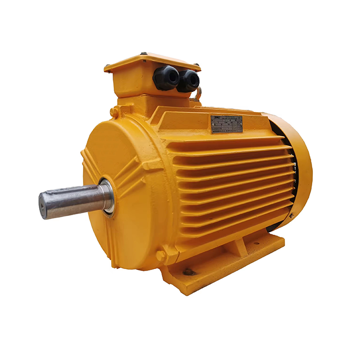
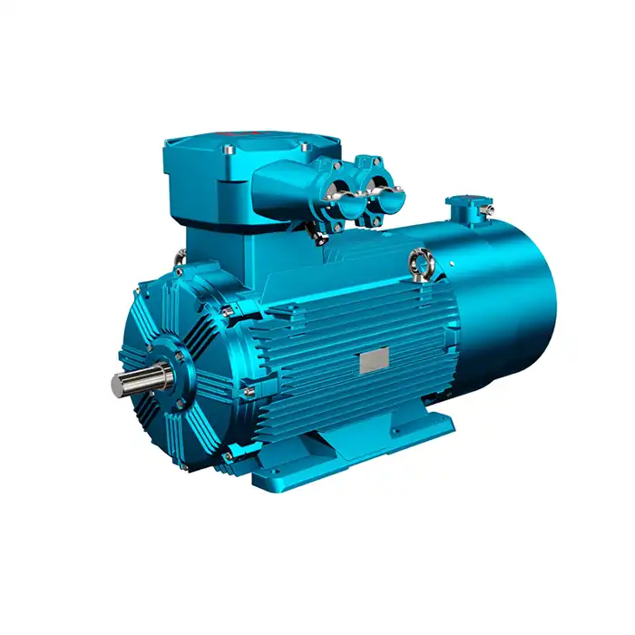
Series:Z2
Frame number: 11-112
Application:Z2 series motors are small DC motors for general industrial use and can be used in metal cutting machine tools, papermaking, dyeing and weaving, printing, cement, etc. The generator can be used as power source, lighting or other constant voltage power supply.
Power range:0.8-200kW
Voltage range: 110V,220V, etc.
Certificate: standard JB1104-68 .
Advantage:Suitable for outdoor use and strong corrosion resistance.
Others: SKF, NSK, FAG bearings can be replaced according to customer requirements.
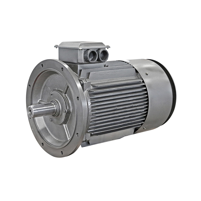
Understanding 15kW DC Motor Fundamentals
DC motors convert electrical energy into mechanical motion through electromagnetic principles. A 15kW electric motor operates at considerable power levels, requiring robust electrical infrastructure and careful thermal management. These units typically operate within voltage ranges of 110V to 220V, depending on application requirements.
Motor specifications play a crucial role in installation planning. Understanding torque calculation, load capacity, and speed control requirements helps determine the optimal mounting configuration. Industrial applications often demand motors capable of handling variable loads while maintaining consistent performance.
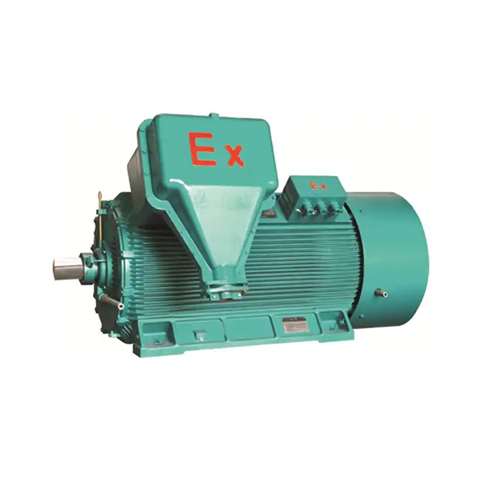
The Z2 series motors excel in general industrial use across metal cutting, papermaking, textile manufacturing, and cement production. Their outdoor-suitable design and corrosion resistance make them ideal for challenging environments. Power ranges from 0.8kW to 200kW accommodate diverse operational needs.
Pre-Installation Planning and Site Assessment
Evaluation of the site in its entirety is the first step toward successful motor installation.
- There is a substantial relationship between environmental conditions and the performance and lifetime of motors. Environmental factors like as swings in temperature and humidity, as well as exposure to chemicals or toxins, all have a role in the selection of protective measures and equipment.
- The evaluation of the electrical infrastructure guarantees that there is sufficient capacity for power delivery. It is necessary for voltage control systems to be able to manage the starting current and operating requirements of the motor. It is necessary to size DC motor controllers appropriately and verify their interoperability with the control systems that are already in place.
- In addition to the motor footprint, space requirements are also necessary. Access for maintenance, ventilation clearances, and the possibility of gearbox integration are all factors that need careful study. It is essential for motor cooling systems to have unimpeded airflow in order to avoid overheating during continuous operation at all times.
- The preparation of the foundation entails the creation of a mounting surface that is both sturdy and resistant to vibration. Bearing wear may be reduced and motor life can be extended by proper alignment. The early failure of spinning components may be avoided by ensuring that the leveling accuracy meets the criteria of the manufacturer.
Essential Safety Protocols and Personal Protection
- Electrical safety is the foundation upon which each and every motor installation technique is built. During the installation process, lockout and tagout processes prohibit the unintentional energization of the system. Isolation and verification are necessary for a variety of energy sources, including control circuits and auxiliary power.
- For example, insulated gloves, safety eyewear, and footwear that does not conduct electricity are all examples of personal protection equipment. In the course of connection processes, arc-rated apparel offers protection against the dangers posed by electrical flashes. Hard helmets and safety harnesses can be required during the installation, depending on the height of the installation and the surroundings.
- The standards for team communication guarantee that the actions of the team are coordinated throughout the lifting and positioning operations. Accidents associated with the operation of heavy machinery may be avoided by using clear verbal signals and authorized spotters. Throughout the whole of the installation process, emergency measures and first aid services have to be easily available.
- In order to avoid personal harm and damage to equipment, it is important to pick and evaluate tools appropriately. Wrenches that are calibrated according to the manufacturer's standards guarantee that the fastening tension is accurate. During the process of connecting circuits, the danger of electrical shock is reduced by insulated tools.
Mechanical Installation Procedures
Motor mounting begins with foundation inspection and preparation. Anchor bolt placement must align precisely with motor foot dimensions. Grouting materials should cure completely before motor positioning to prevent settling or misalignment.
Lifting equipment capacity must exceed motor weight with appropriate safety margins. Rigging points on the motor housing distribute lifting forces evenly. Soft slings prevent damage to painted surfaces and precision-machined components.
Shaft alignment requires precision instruments and careful adjustment. Angular and parallel misalignment create excessive bearing loads and reduce motor life. Coupling installation follows manufacturer specifications for gap dimensions and bolt torque values.
Vibration dampening methods may include flexible mounts or isolation pads. These components prevent transmission of motor vibrations to supporting structures. Proper installation maintains alignment while reducing noise levels in occupied areas.
Electrical Connections and Power Supply Integration
Power cable sizing must accommodate motor starting current and operational loads. Voltage drop calculations ensure adequate power delivery under all operating conditions. Conduit systems protect wiring from environmental damage and provide organized cable routing.
Terminal box connections require careful attention to polarity and phase sequence. Proper torque application prevents loose connections that could cause arcing or overheating. Heat-shrink tubing or insulating tape provides additional protection for exposed connections.
Grounding systems establish safe electrical paths for fault currents. Equipment grounding conductors connect motor frames to facility ground systems. Proper grounding reduces electrical shock hazards and improves system reliability.
Control circuit integration involves connecting speed control systems, emergency stops, and monitoring devices. DC motor controllers require programming to match motor characteristics and application requirements. System testing verifies proper operation before full commissioning.
Cooling and Ventilation Considerations
Motor cooling systems prevent overheating during continuous operation. Forced air cooling requires unobstructed intake and exhaust paths. Filter maintenance schedules keep cooling systems operating at peak performance levels.
Ambient temperature monitoring helps optimize cooling system operation. Temperature sensors provide early warning of potential overheating conditions. Thermal protection devices automatically shut down motors before damage occurs.
Enclosure ventilation maintains acceptable internal temperatures. IP55 protection ratings balance environmental sealing with cooling requirements. Proper ventilation design prevents condensation buildup that could damage electrical components.
Performance optimization involves balancing cooling effectiveness with energy consumption. Variable speed fans reduce power consumption during light-load conditions. Temperature-based control systems adjust cooling capacity to match operational demands.
Testing and Commissioning Procedures
Initial testing begins with insulation resistance measurements. Megohm readings verify winding integrity and identify potential moisture or contamination issues. Values below manufacturer specifications require investigation and remediation before energization.
No-load testing confirms proper motor rotation and absence of mechanical interference. Current measurements during no-load operation establish baseline values for future comparison. Unusual noise or vibration levels indicate potential installation issues requiring correction.
Load testing demonstrates motor performance under actual operating conditions. Torque and speed measurements verify compliance with application requirements. Energy conversion monitoring confirms expected motor efficiency levels.
System integration testing validates complete drivetrain operation. Speed control responsiveness and load handling capability demonstrate proper installation and commissioning. Documentation of test results provides baseline data for future maintenance activities.
Maintenance Requirements and Long-term Care
Regular inspections keep motors running well and make them last longer. Visual inspections find signs of wear, contamination, or damage that need to be fixed. Vibration analysis finds problems with bearings before they break down completely.
Lubrication programs keep bearings working within the limits set by their design. Using high-quality lubricants and applying them at the right times may help avoid wear and tear. When maintenance is needed, SKF, NSK, and FAG bearing replacements make sure that things keep working.
Monitoring the electrical system keeps an eye on the resistance of the insulation and the strength of the connections. Thermal imaging may find hot patches that indicate weak connections or too much resistance. Preventive maintenance keeps things from breaking down unexpectedly and costing you time and money.
Performance trending finds little problems that need to be fixed over time. Monitoring energy use shows that motors are becoming less efficient. Early intervention prevents little problems from turning into big ones.
Conclusion
Successful 15kW DC motor installation requires comprehensive planning, strict safety adherence, and precise execution. Proper mechanical mounting, electrical connections, and commissioning procedures ensure optimal performance and longevity. Regular maintenance schedules preserve investment value while preventing costly downtime. Understanding these fundamental principles enables engineers to maximize motor performance across diverse industrial applications. Professional installation and quality equipment selection create reliable foundations for long-term operational success.
Choose XCMOTOR for Your Industrial Motor Solutions
Shaanxi Qihe Xicheng Electromechanical Equipment Co., Ltd. delivers comprehensive power equipment solutions tailored to your specific requirements. Our commitment extends beyond product delivery to include technical support, installation guidance, and ongoing maintenance assistance.
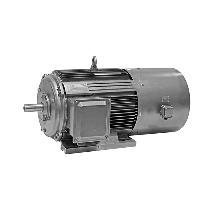
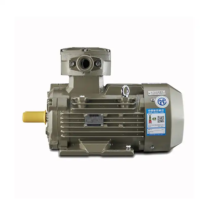
XCMOTOR's Z2 series 15kW DC motors combine proven reliability with advanced engineering. These robust units feature high-grade steel shafts, precision-wound armatures, and superior insulation systems. Operating temperatures from -20°C to +40°C accommodate diverse industrial environments.
Our quality assurance program includes rigorous testing and international certifications. CE and CCC compliance demonstrates adherence to global safety and performance standards. Deep groove ball bearings and forced air cooling systems ensure reliable operation across demanding applications. Customer support includes weekend availability and comprehensive technical assistance. Our engineering team provides application guidance, installation support, and troubleshooting expertise. Fast delivery and 30-day return policies minimize project delays and risk.
Competitive advantages include original parts from trusted brands and stable power output across variable loads. Energy-efficient designs reduce operational costs while maintaining superior performance. Whether you need a 15kw dc motor manufacturer or ongoing technical support, contact us at xcmotors@163.com to discuss your specific requirements and receive personalized recommendations.
References
- International Electrotechnical Commission. "Rotating Electrical Machines - Part 1: Rating and Performance Standards." IEC 60034-1, 2022 Edition.
- National Electrical Manufacturers Association. "Motors and Generators Installation and Maintenance Guidelines." NEMA MG 1-2021 Standard.
- Institute of Electrical and Electronics Engineers. "Recommended Practice for Electric Power Systems in Commercial Buildings." IEEE 241-1990 (Reaffirmed 2019).
- Occupational Safety and Health Administration. "Control of Hazardous Energy - Lockout/Tagout Safety Standards." OSHA 1910.147 Compliance Guide.
- American Society of Mechanical Engineers. "Power Transmission and Distribution Safety Code for Industrial and Commercial Applications." ASME B15.1-2020.
- International Organization for Standardization. "Vibration and Shock - Mechanical Vibration of Rotating and Reciprocating Machinery." ISO 20816-1:2016 Standard.