




Slip Ring Motor Working Principle: Rotor Resistance
A slip ring motor — formally called a wound rotor induction motor — controls starting torque and current by connecting the rotor windings to external resistance through slip rings and carbon brushes. When resistance increases in the rotor circuit, starting torque rises while inrush current stays low. As the motor accelerates, resistance steps down gradually, allowing smooth speed transitions. This design makes the slip ring motor well-suited for heavy-load, high-frequency start-stop applications where a standard squirrel cage motor would overstress the power supply or fail to deliver adequate torque at low speed.
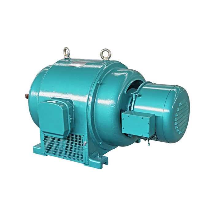
Series:YRQ
Voltage range:380V±5%
Power range:45-710kW
Protection level:IP23
Application:YRQ(JR) series medium-sized motors can drive a variety of different machinery, such as fans, compressors, water pumps, crushers, ball mills, cutting machine tools, transportation machinery and other equipment, and can be used in coal mines, machinery industries, power plants and various industrial and mining enterprises. Used as prime mover.
Advantage: The JR series medium-sized motors have very powerful driving capabilities and can not only drive conventional mechanical equipment, but also some complex mechanical equipment. For example, it can drive heavy machinery such as ships, cranes, and wind turbines, as well as small household appliances, purifiers, compressors, etc.
Others: SKF, NSK, FAG bearings can be replaced according to customer requirements.
Understanding the Slip Ring Motor Working Principle
Core Components and Their Roles
There are three main parts that make up a wound rotor induction motor. They are the stator, the rotor, and the slip ring assembly. There are three-phase AC windings in the stator that make a rotating magnetic field. The rotor has wound copper coils inside it, not cast aluminum bars. The ends of the coils connect to three slip rings on the shaft that are outside the rotor. These rings are pressed against by stationary carbon brushes, which creates an electrical path to an outside resistance bank. This setup lets researchers get to the rotor circuit directly, which isn't possible with a squirrel cage design.
How Rotor Resistance Shapes the Torque-Speed Curve
When resistance is added to the rotor circuit, the peak torque point moves toward a slower speed. The torque-slip curve peaks close to zero RPM when the motor is at rest because the rotor has more resistance. This gives the load a lot of pull-out torque just when it needs it the most. As the motor goes faster, the resistance is lowered little by little. This keeps the torque high and the current under control. IEEE Standard 620 says that wound rotor motors can start with starting currents below 2.5 times their rated current and starting torques of 2.0 to 3.0 times their rated torque. Squirrel cage motors, on the other hand, can't match this ratio without a variable frequency drive.
Induced EMF, Slip, and Rotor Current
Slip is the difference, shown as a percentage, between the synchronized speed and the spinning speed. Slip is 100% when the motor is at rest, and rotor-induced EMF is highest. A strong electromagnetic field (EMF) causes a large current to flow through the rotor. The external resistance takes this current so it doesn't cause damage on the supply side. As speed goes up, slip goes down, induced EMF goes down, rotor current goes down naturally, and the external resistance bank can gradually short out. Knowing this connection helps technical buyers choose the correct resistance steps for lifting, moving, or ramping up a conveyor belt.
Key Advantages of Slip Ring Motors Due to Rotor Resistance
High Starting Torque at Low Inrush Current
Slip ring motor external rotor resistance's main benefit is that it lets you make a lot of starting power without drawing too much current from the grid. The 5–7× inrush that a squirrel cage motor makes is often too much for the electrical systems in steel mills, port cranes, and mining hoists to handle. This can only happen at 2–3× rated current in a wound rotor motor, which still gives 1.8–2.5× rated starting torque. When OEM crane makers order bridge cranes and gantry cranes together, they don't need to buy a separate soft-starter or variable frequency drive. This saves up to 30% on the cost of the system.
In heavy-duty start-stop service, these are the most important performance traits:
- Controlled inrush current: Starting current stays at 2–3× rated, protecting switchgear, cables, and transformers from thermal stress during repeated start cycles exceeding 120 times per hour.
- Adjustable torque characteristic: Operators can tune the external resistance bank to match load inertia, preventing shock loads on gearboxes and couplings during every start.
- Stepped acceleration: Resistance is removed in stages, producing smooth speed ramps that improve positioning accuracy on crane bridges and hoists.
Because of these qualities, infrastructure costs go down, drivetrains last longer, and there are fewer unplanned shutdowns in tough production settings.
Smooth Low-Speed Operation
The motor stays at the same speed even when the load changes because the rotor resistance keeps the torque-speed relationship almost flat at low slip values. This stability is good for elevator main drives and hoist drums because it stops speed hunting that would happen if the load moved around while lifting. This is possible with XCMOTOR's YRQ series wound rotor motor, which has multi-strand copper rotor windings and precision-machined slip ring assemblies. It has consistent low-speed behavior across its 45–710 kW power range.
Brake Integration and Stop Precision
Controlled braking can also be done with external force. By adding resistance again before the mechanical brake is used, operators lower the amount of kinetic energy that the brake has to take in. This makes the brake pads last a lot longer and makes it easier to get back to the same stop position. This is one of the most important factors that procurement engineers at crane OEMs always look at along with starting torque multiples.
Slip Ring Motor vs. Other Motor Types: Focus on Rotor Resistance and Efficiency
Wound Rotor vs. Squirrel Cage Construction
A squirrel cage induction motor has bars made of cast aluminum or copper that are connected at both ends by end rings. The rotor circuit can't be reached from the outside. So, the starting current is always high (usually rated between 5 and 7×), and the starting torque is always the same because of the way the rotor bars are shaped. This level of simplicity is good for light, steady loads like fans and pumps that run at a steady speed. The squirrel cage design means that engineers have to add a variable frequency drive to crane hoists, ball mills, and crushers that start up under full load over and over again. This adds cost and a possible failure point.
Where Rotor Resistance Control Changes the Decision
The wound rotor motor is a simpler way for procurement teams to handle heavy starting duty. There are no harmonics to protect the inverter power electronics from, no DC bus capacitors to repair, and no need for a drive case to be cooled. The external resistance box is an inactive part that doesn't have any chips in it. When replacing old motors from major European or Asian brands in service bays of cement plants and steel mills, the wound rotor design keeps the existing resistance cabinet, which lowers the cost of the changeover and the time it takes to complete.
Efficiency Trade-off: Practical Perspective
When the load is fully applied, wound rotor motors are 1% to 2% less efficient than similar squirrel cage designs. This is because the rotor circuit still has resistance losses even when the external bank is shorted. However, this trade-off is fine for high-cycle uses where the motor spends a lot of time speeding up instead of working at steady state. When you get rid of a variable frequency drive and cut down on infrastructure updates, you usually make up for the lost efficiency in the first year of operation.
Practical Applications and Maintenance Related to Rotor Resistance
Industrial Scenarios That Fit the Wound Rotor Design
The YRQ (JR) series wound rotor motor can be used for many things. It turns crushers and ball mills that start up with a full load in coal mines and places that process metal ore. Bridge and gantry cranes in port terminals and steel distribution centers use it to power their loads, which change every time the crane lifts. In cement plants, it powers systems that move raw materials and need to start up slowly to protect the belt splices. Idled draft fans in power plants use it to start up, even though the system is resistant. The YRQ series is suitable for indoor and semi-protected industry settings in all of these fields thanks to its 45–710 kW power range and IP23 protection level.
Maintenance Practices for Long Service Life
Maintenance for slip ring motor slip rings and brushes is easy if you plan it right. The carbon brushes wear down at a steady rate, and they should be checked every 1,000 to 2,000 hours of use, depending on how often the machine is started. The rotor circuit resistance is directly affected by the contact pressure of the brushes and the condition of the rings. Worn brushes or oxidized rings add resistance that wasn't meant to be there, which changes the torque curve. When you add up all the costs of owning a motor, the amount of money you spend on repair each year for a wound rotor motor is usually between 6 and 9 percent of the price you paid for it.
Important repair jobs that keep rotor resistance strong are:
- Brush inspection and replacement: Check brush length, contact pressure, and ring surface finish. Replace brushes before they reach minimum length to avoid ring scoring.
- Slip ring cleaning: Remove carbon dust buildup with dry compressed air and wipe rings with a lint-free cloth. Pitting or grooves require ring resurfacing.
- External resistance bank verification: Measure each resistance step with a calibrated ohmmeter at commissioning and annually. Verify thermal capacity matches the actual start cycle frequency.
Record all readings and compare them to the factory test report once these checks are done. This will help you find drift before it affects production. Every YRQ series motor comes with a factory test report that includes waveform data. This gives maintenance teams a reliable starting point to work from when they need to make changes.
Troubleshooting Rotor Resistance Problems
Uneven acceleration, higher-than-expected starting current, or strange brush sparking are all common signs of problems with the rotor circuit. Most of the time, uneven acceleration means that there is an open resistance step in the external bank. A high starting current means that the rotor resistance isn't high enough; check the brush contact. Brush sparking above normal levels could mean that the ring surface is rough or that the brush grade is wrong. Premium bearings from SKF, NSK, or FAG can be added as options to YRQ series motors. These reduce shaft vibration, which speeds up the wear and tear on the brushes and rings.
Procurement Guidance: Choosing and Buying Slip Ring Motors with Rotor Resistance Considerations
Technical Specifications to Verify Before Purchase
Before making a purchase of a wound rotor induction motor for a crane, hoist, or mill, make sure you check these specifications:
- Starting torque multiple must reach at least 2.0× rated torque, with 2.5× preferred for full-load starting in crane service.
- Starting current multiple should not exceed 2.5–3.0× rated current to stay within typical switchgear ratings.
- Start-stop frequency rating must match the application duty cycle; crane service commonly requires 120 or more starts per hour.
- Confirm that the external resistance box specifications — resistance values, thermal rating, and step count — match the new motor's rotor circuit parameters if reusing existing equipment.
- For replacement jobs, verify shaft extension diameter, keyway dimensions, and foot mounting pattern against the original machine drawing before ordering.
By matching these parameters, you can avoid having to redo the installation and be sure that the existing resistance cabinet will work right with the new motor from the start.
What the YRQ Series Offers Procurement Teams
The YRQ series wound rotor motor from XCMOTOR can handle 45–710 kW at 380V ±5%. It has IP23 protection, Class B insulation (temperature rise below 120°C), and can handle 3–4× of maximum power for 15–30 seconds of overload. A factory test record with waveform data, insulation resistance values, and vibration measures is included with the motor when it is shipped. It has been certified by CCC, CE, ISO9001:2000, CRCC, and CQC. You can ask for bearing options from SKF, NSK, or FAG. This helps customers who need to match OEM bearing specs for standardizing spare parts.
Conclusion
In conclusion, rotor resistance plays a vital role in the working principle of slip ring motors. By adding external resistance to the rotor circuit, these motors can achieve high starting torque, reduce starting current, and provide smooth acceleration. Although rotor resistance control offers effective speed regulation, it also increases energy losses. Understanding this principle helps engineers optimize motor performance, improve operational efficiency, and select suitable solutions for various industrial applications.
FAQ
1.How does rotor resistance affect starting torque in a wound rotor motor?
When the motor is at rest, it produces more starting torque—up to 2.5× rated in the YRQ series—while drawing only 2–3× rated current instead of the 5–7× rated current that squirrel cage designs usually do. This means that the wound rotor motor is the standard way to start a crane or mill when it is fully loaded.
2.Can the external resistance be adjusted after the motor is installed?
Yes. The external resistance bank is linked to the rotor by slip rings and brushes, which means that resistance values can be changed at any time. If the load profile changes, like when a crane is upgraded to carry heavier loads, the resistance steps can be changed without having to change the motor itself. To keep the rotor circuit from getting too hot, always make sure that the new resistance values fit the circuit's requirements.
3.What are the signs that rotor resistance has changed unexpectedly?
Keep an eye out for rapid or uneven acceleration, starting current numbers that are higher than usual, or sparking that you can see at the brush-ring contact that is higher than usual. Most of the time, these signs mean that the brushes are worn out, the ring surface is breaking down, or the resistance step is open or shorted. Using an ohmmeter to compare the rotor circuit resistance to the factory baseline values will help you quickly find the problem.
4.How often do slip rings and brushes need replacement?
How often you start the brush depends on how often you inspect it. Every 1,000 to 1,500 hours of use, check the brushes on a crane that starts 120 times an hour. The cost of annual maintenance is usually between 6 and 9 percent of the price of the motor itself. This is a predictable cost that fits into most budgets for plant maintenance.
Get the Right Wound Rotor Motor for Your Application — Contact XCMOTOR
There is a team at XCMOTOR ready to help you find the right YRQ series slip ring motor for your crane, hoist, mill, or conveyor project. We ship quickly, let you return items within 30 days, offer original brand bearings, and include certified factory test reports with every order. You can look at the full specs at motorxc.com, or you can email your technical needs directly to xcmotors@163.com to get a quick quote and engineering review.
References
1. IEEE Standard 620, IEEE Guide for the Presentation of Thermal Limit Curves for Squirrel Cage Induction Machines, IEEE, 2008.
2. Chapman, S. J., Electric Machinery Fundamentals, McGraw-Hill Education, 2012.
3. Wildi, T., Electrical Machines, Drives, and Power Systems, Pearson Prentice Hall, 2006.
4. Boldea, I. and Nasar, S. A., The Induction Machine Handbook, CRC Press, 2002.
5. IEC 60034-1, Rotating Electrical Machines — Part 1: Rating and Performance, International Electrotechnical Commission, 2017.
6. Mohan, N., Undeland, T. M., and Robbins, W. P., Power Electronics: Converters, Applications, and Design, John Wiley & Sons, 2003.
YOU MAY LIKE
 VIEW MOREykk motor
 VIEW MOREYXKK series high voltage and high efficiency motor
 VIEW MOREYR(IP23) series high voltage wound rotor three-phase asynchronous motor
 VIEW MOREslip ring rotor motor
 VIEW MORE3 phase inverter duty motor
 VIEW MOREmotor ip23
 VIEW MORE6kv slip ring motor
 VIEW MOREYBS low voltage explosion-proof coal mine motor