



12 Swing Check Valve Installation: Key Steps for Reliable Flow
Installing a swing check valve correctly is essential for protecting pumps, preventing backflow, and ensuring system reliability in municipal water treatment, power generation, and industrial fluid projects. The 12 swing check valve from XCMOTOR's H44 series (DN20-DN600, PN16/25/40) combines robust ductile iron or SS316 construction with EPDM sealing to deliver dependable performance across freshwater and saltwater applications. Proper installation minimizes water hammer risks, avoids flange misalignment, and extends valve service life to 100,000 cycles, making it indispensable for procurement managers overseeing large-scale pipeline projects.
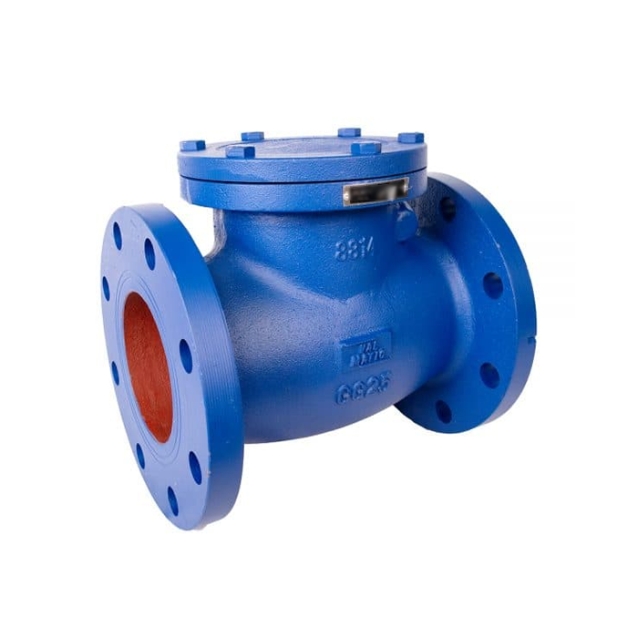
Series:H44
Diameter:DN20~DN600,
PN:16;25;40
Application specification: Design, manufacture:GB/T12236 Length of the structure:GB/T12221 Connecting flange: JB/T79 Valve inspection and test:JB/T9092
Understanding the Basics of Swing Check Valves
What Is a Swing Check Valve and How Does It Work?
A swing check valve stops flow from going the wrong way by using a flexible disk that swings open when fluid moves in the right direction and closes itself when flow stops or goes the wrong way. This system keeps upstream equipment, like pumps and compressors, safe from backflow, which is very important in water treatment plants, cooling water circuits, and oil platforms at sea. Lift check valves depend on moving vertically, but swing designs offer lower pressure drop and smoother operation, which means they use less energy in systems with a lot of flow (Valve Magazine, 2021).
The H44 series swing check valve works by using gravity and difference in pressure. When forward flow starts, the fluid pushes the disk away from the seat, making room for it to move through the full-bore construction. When the flow stops, the disk closes itself and stays closed under its own weight. This makes a tight seal that stops backflow. This passive operation doesn't need any outside power, so it works even when the power goes out. This is a big plus for municipal water supply projects in places where the energy infrastructure isn't solid.
Material Selection and Its Impact on Performance
The type of material you choose has a direct effect on how well it resists rust, how strong it is, and how well it works in certain settings. For freshwater uses like city supply and wastewater treatment, ductile iron bodies last a long time. On the other hand, SS316 stainless steel versions work great in saltwater settings like desalination plants and offshore drilling platforms. EPDM disk seals don't break down chemically when they come in contact with chlorinated water and industrial fluids, so they keep working properly for a long time (API 6D Standard, 2018).
The design of the valve also affects its weight and how easy it is to place. A DN300 (12-inch) swing check valve made of ductile iron usually weighs between 80 and 120 kg, so it takes a team working together and the right lifting gear. Stainless steel versions may weigh a little less, but they are better at stopping sulfide stress cracks in sour gas conditions, as proven by NACE MR-0175. When projects go through oilfields in the Middle East, wastewater treatment plants in Southeast Asia, or mines in Latin America with very different environmental conditions, these material properties become very important.
Pressure Ratings and Certification Requirements
For industrial projects, valves must meet international standards for keeping pressure in and keeping workers safe. The H44 series can handle PN16, PN25, and PN40 ratings according to GB/T12236 design standards. These ratings are the same as the ANSI 150/300 class ratings used in North American standards. This two-way compatibility makes buying things easier for international workers who are in charge of projects in different regulatory areas. According to API 598 standards, valves that are certified with API 6D can survive pressure tests. These tests include hydraulic shell tests at 1.5 times the rated pressure and seat leak tests at 1.1 times the rated pressure (ISO 9001 Quality Management, 2020).
When responding to bid requests from government agencies or international EPC contractors, certification documents are very important. Following the JB/T9092 guidelines for valve inspection and testing makes it possible to track through material certificates, dimensional reports, and pressure test records. This paperwork shows that the rules were followed during third-party inspections. This keeps the project on track and prevents expensive rework when equipment gets to job sites in Africa or the Middle East that are far away.
Step-by-Step Guide to Installing Your Swing Check Valve
Pre-Installation Inspection and Preparation
Before you start installing the 12 check valve, make sure that it fits the project's size, pressure number, and flange standard requirements. Pay close attention to the flange faces, disk movement, and hinge pin integrity as you check the valve body for shipping damage. If you place the valve backward, it will fail right away and could damage other equipment. This is because the flow direction arrow that is cast into the valve body must line up with the flow direction in the pipeline. Take off the protective caps that are on the flange faces and look at the seating surfaces for any debris or corrosion that might make it harder for the gasket to seal.
In order to prepare a pipeline, the flange sides must be clean and free of welding splatter, rust, and old gasket material. Clean the matching surfaces with a wire brush and solvent. Then, use a straightedge to make sure the flanges are lined up correctly. Incorrectly matched flanges cause uneven bolt loads, which can cause valve bodies to crack when pressure is applied and removed. To keep the valve body from being stressed mechanically, make sure that the pipe supports are properly holding the system's weight. This step is especially important in pump discharge lines, where vibrations and sudden changes in pressure create dynamic loads that are higher than what was calculated in the static design.
Positioning and Orientation Considerations
For swing check valves, the standard setup is horizontal installation, with the hinge pin facing the opposite direction of flow. In this position, gravity helps the disk close, which speeds up response times and improves sealing. Vertical systems with upward flow are fine, but they might need designs with springs to make sure they close reliably, especially when the flow speed is low. Don't put in downward vertical flow systems because gravity makes it hard for the disk to close, which leads to leak risks that defeat the valve's purpose (Water Treatment Engineering Handbook, 2019).
Clearance standards must take into account the disk swing radius and how easy it is to do upkeep. Leave at least 300 mm of room around the body of the valve so that it can be taken apart and replaced in the future. Place the valve 5 to 8 pipe diameters downstream of the pumps to allow the flow to stabilize and lessen the effects of turbulence on disk operation. If you install the valve too close to the pumps, it will be exposed to pressure pulses that wear down the hinge pins and sitting surfaces faster. This cuts the service life from 100,000 cycles to less than 50,000 cycles.
Gasket Installation and Bolt Torquing Sequence
Choose seals that can handle the chemicals and temperatures in your system. EPDM or nitrile rubber gaskets work well in water systems that are between -20°C and 120°C. Graphite-reinforced gaskets, on the other hand, can handle higher temperatures in systems that use steam or hot oil. Place gaskets so that they are all centered on the flange sides. Make sure that the gaskets don't stick out into the flow path and stop the disk from moving. Use gaskets with the right compression rate. Gaskets that are too compressed will pop apart under pressure, while gaskets that are too compressed will let air leak through.
Put all of the flange bolts in place before tightening any of them. To get accurate torque values, grease the threads of the bolts. In a star design, tighten the bolts three times: the first time, to 30% of the total torque, the second time, to 60%, and the last time, to 100%. This method makes sure that the seal is compressed evenly and stops the ring from warping. Final torque values for DN300 flanges with M24 bolts are usually between 400 and 500 Nm, but you should always check the manufacturer's specs because different types of materials affect how properly they should be loaded. After 24 hours of use, check the torque values again because seals settle down from changing pressure and temperature.
Post-Installation Testing and Commissioning
Before putting the system to use, it should be tested for pressure. Fill the pipeline slowly while letting out any trapped air through high-point valves. Then, use water or hydraulic fluid to raise the pressure to 1.5 times the working pressure. Hold the test pressure for 30 minutes while you check all of the joints for leaks. Listen for the typical click as the disk seats to make sure it moves freely during the initial flow. Any other noise could mean that there were problems with the installation or that there is debris inside the disk.
To make sure the check valve works right, do a flow reversal test. Once the pressure in the upstream is gone, try to make backflow happen and make sure the disk shuts against it. Keep an eye out for leaks past the seat. The rate of leaks should not go over the 40 drops per minute that API 598 allows for metal-seated valves. Write down all of the test results, such as the pressure numbers, length of time, and temperature of the environment. This information will be part of the project quality records that need to be given to the facility workers.
Common Installation Mistakes and How to Avoid Them
Incorrect Flow Direction and Its Consequences
The most common fitting mistake is still putting valves in backward, which makes the check feature useless right away. Backflow will make the disk open instead of closing against it, letting reverse flow happen. This can damage pumps through hydraulic shock and reverse rotation. Installers often make this mistake when they don't pay attention to the flow arrow or when they use old models that show the wrong direction. Always compare the flow direction to isometric models of the pipe, and check the arrow that is cast into the valve body twice before you weld the flanges or tighten the bolts.
The cost effects go beyond the cost of replacing the valves. If reverse rotation damages a pump impeller, the whole pump may need to be rebuilt, which can cost $20,000 to $50,000 for large municipal units. When systems are down for emergency repairs, they can affect the water supply or production plans, which puts workers at risk of being sued. This risk can be almost completely eliminated by using a pre-installation checklist that needs boss approval for flow direction confirmation. This protects both project funds and professional identities.
Improper Bolt Torque and Flange Stress
Bolts that aren't tight enough let gaskets break, which loses water, puts people in danger, and corrodes pipes nearby. When bolts are over-torqued, they stretch past their elastic limits. This lowers the clamp load and could cause ductile iron flanges to crack. When the temperature changes, it makes the problem worse because nuts that were tight when the system was at 20°C may become loose when it's at 80°C if the workers don't take thermal expansion coefficients into account.
Using calibrated torque wrenches takes away the need to guess and makes sure that all installers get the same results. For large bolts bigger than M30, hydraulic tensioning tools give even more accurate results, but they cost more to buy at first. Teaching construction crews the right way to torque things pays off by cutting down on warranty claims and callbacks. One city contractor said that the number of flange leaks dropped by 85% after all field workers were required to get torque wrench certification (Pump & Systems Magazine, 2020).
Material Incompatibility and Corrosion Failures
Material incompatibility can cause galvanic corrosion and premature joint failure, such as carbon steel bolts with stainless flanges or zinc-coated hardware in chlorinated water. Proper material pairing based on the galvanic series is essential for 12 check valve. Protective coatings, compatible anti-seize compounds, and clearly specified materials for every component improve long-term reliability in harsh environments.
Maintenance Strategies for Long-Term Valve Reliability
Inspection Schedules and Key Performance Indicators
Inspection frequency should reflect operating severity, ranging from annually for low-flow services to quarterly for high-cycle applications. Inspections should check corrosion, packing leaks, abnormal sounds, and disk movement. Trending differential pressure and external position indicators can reveal fouling, misalignment, or backflow issues early, supporting condition-based maintenance and reducing unexpected repairs.
Cleaning and Lubrication Best Practices
Annual cleaning removes mineral deposits and bacterial buildup that restrict valve movement and closing. Safe, material-compatible cleaners, brushing, and hinge-pin inspection help prevent damage. Lubrication requirements depend on valve design; bushed hinges need compatible, water-resistant grease, while self-lubricating polymer bushings require periodic wear checks. Avoid over-lubrication and follow manufacturer guidelines to prevent contamination and seal damage.
Troubleshooting Common Operational Issues
Valve chatter occurs when flow is insufficient to keep the disk open, causing noise, vibration, and seat wear. Solutions include smaller valves, spring loading, or improved piping. Water hammer creates severe pressure spikes; slower-closing or hydraulic damping systems can reduce them. Spring-assisted checks have reduced peak pressure from 18 to 8 bar in practice.
Selecting the Right Swing Check Valve for Your Application
Pressure Rating and Size Determination
Valve selection should match maximum system pressure, including surges, with ratings at least 20% above the expected limit. H44 valves offer PN16, PN25, and PN40 options for common applications. Proper sizing minimizes pressure loss and energy costs, while undersizing may create significant long-term pumping expenses despite lower initial purchase costs.
Material Selection for Specific Operating Conditions
Material selection should balance operating conditions, corrosion resistance, strength, and lifecycle cost. Ductile iron suits neutral water systems, while epoxy coatings improve durability in mildly corrosive environments. SS316 is appropriate for seawater, chemicals, and higher temperatures. Duplex stainless steel, nickel alloys, and bronze serve specialized conditions where superior corrosion resistance and long-term savings justify higher costs.
Supplier Evaluation and Procurement Considerations
Reliable suppliers should demonstrate certifications such as API 6D, ISO 9001, and CE, supported by documented quality controls and SAP-based production tracking. Customization of flange standards, materials, and coatings enables project-specific solutions. Fast customization benefits urgent projects, while orders exceeding 100 units may receive 15–25% volume discounts, reducing overall costs.
Conclusion
When 12 swing check valve are installed and maintained correctly, they protect important infrastructure investments and make sure that fluid systems work reliably in places like power generation, municipal water treatment, and industrial process applications. Common failures that hurt system performance can be avoided by following organized installation procedures, such as a full pre-installation check, correct orientation, gasket selection, and accurate bolt torquing. When you choose materials that are right for the job and do regular upkeep based on performance tracking instead of making up random schedules, you can extend the life of the equipment and lower the total cost of ownership. Instead of just looking at the price, procurement workers should look at a supplier's certifications, ability to customize, and support services. The H44 series swing check valve, which is made to GB/T12236 standards and comes in sizes DN20 to DN600 and pressure ratings PN16 to PN40, is reliable and adaptable enough for tough international projects.
FAQ
1.How do I verify correct flow direction before installation?
Check the arrow that points in the direction of flow that is cast or stamped into the valve body. This is usually on the side near the input lip. This arrow needs to point in the same direction that the fluid is moving through your pipe. Compare with piping isometric plans and check with project engineers if you're not sure, because if you place the valve wrong, it won't work.
2.What materials work best for offshore saltwater applications?
The bodies are made of SS316 stainless steel and have EPDM seals that keep them from corroding in saltwater environments like offshore oil platforms and coastal power plants. The NACE MR-0175 standards for sour gas service are met by these materials, and they don't crack under salt stress, which is what breaks down lower-grade stainless steels in marine settings.
3.Can swing check valves be installed vertically?
It's fine to install something vertically with upward flow, but the closure may need to be helped by a spring for it to work reliably at low flow rates. Do not install backward vertical flow systems because gravity makes it hard for the disk to close, which can cause backflow problems. Always check the manufacturer's instructions to see if there are any limits on direction or effects on performance.
4.What torque values should I use for flange bolts?
Limits on torque depend on the size of the bolt, the type of material, and the number of the joint. For most valve models and materials, the values for M24 bolts on DN300 PN25 flanges are between 400 and 500 Nm. However, you should check the valve manufacturer's installation manual to be sure. To make sure the gasket is compressed evenly, use torque wrenches that have been measured and follow a star design.
Get Professional Support from XCMOTOR for Your Next Project
XCMOTOR specializes in making high-quality swing check valves for water systems in cities, industrial pumping stations, and fluid systems in the ocean. Our H44 series valves, which are made to GB/T12236 standards and come in sizes from DN20 to DN600, are made of ductile iron, SS316, and EPDM for reliable performance in a wide range of working situations. Every valve goes through ASTM-certified material inspection, precise CNC machining, and hydrostatic testing according to API 598 protocols. This makes sure that bulk orders have defect rates of less than 2%.
As a maker with a lot of experience in making 12 swing check valves, we help foreign contractors by offering customizable flange standards (ASME B16.5/EN 1092), pressure ratings from PN16 to PN40, and changes that can be made within 7 days. Orders of more than 100 units are shipped within 15 to 30 days and come with all the paperwork needed for third-party checks, such as material certifications, measurement reports, and pressure test records. Our technical support team is available 24 hours a day, seven days a week to help with installation and problem-solving.
You can talk to XCMOTOR about your project needs right now by visiting motorxc.com or emailing xcmotors@163.com. Our procurement experts can help you find the best configurations for big infrastructure projects that balance performance and cost-effectiveness, whether you need API 6D-certified valves for foreign bids or custom solutions for pipes that don't follow standard sizes.
References
1. Valve Magazine (2021). "Check Valve Selection and Sizing for Industrial Applications." Valve Magazine Annual Review, pp. 78-84.
2. American Petroleum Institute (2018). API Standard 6D: Specification for Pipeline and Piping Valves, 24th Edition. API Publishing Services, Washington, DC.
3. ISO 9001 Quality Management (2020). "Quality Systems Requirements for Valve Manufacturing." International Organization for Standardization, Geneva.
4. Water Treatment Engineering Handbook (2019). "Backflow Prevention and Check Valve Applications." Water Environment Federation Press, Alexandria, VA, Chapter 12.
5. Pump & Systems Magazine (2020). "Reducing Installation Defects Through Systematic Quality Control." Industrial Media LLC, pp. 34-39.
6. Chemical Engineering Progress (2022). "Water Hammer Mitigation in Process Piping Systems." American Institute of Chemical Engineers, Vol. 118, No. 4, pp. 45-52.