How do inverter duty induction motors handle variable frequency drives (VFDs)?
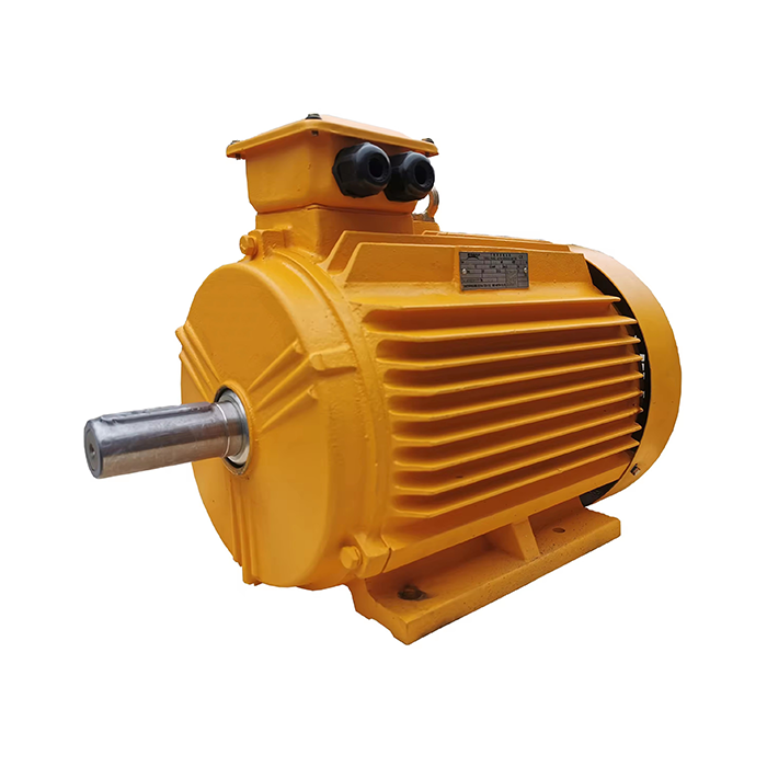
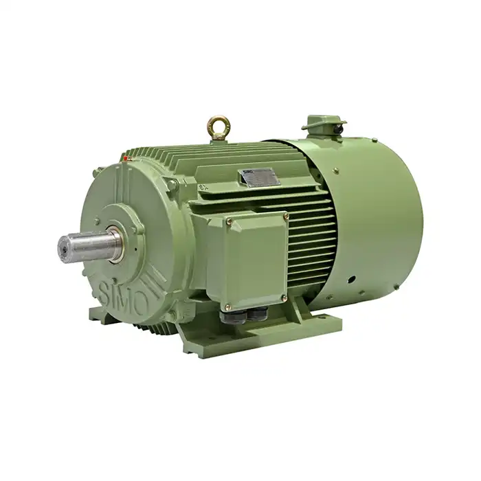
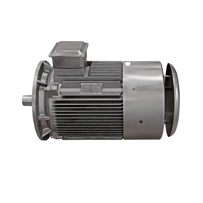
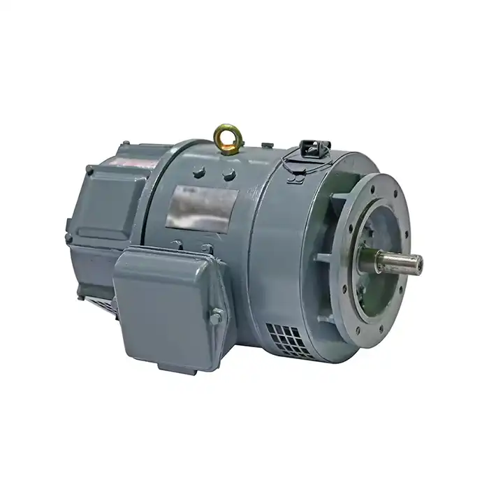
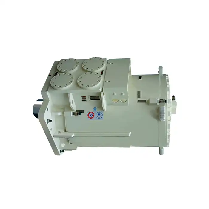
In the world of industrial automation and energy-efficient motor control, inverter duty induction motors have become increasingly prevalent. These specialized motors are designed to work seamlessly with variable frequency drives (VFDs), offering superior performance and longevity in applications that require precise speed control and energy savings. But how exactly do these motors handle the unique challenges posed by VFDs? Let's delve into the intricacies of inverter duty induction motors and explore their relationship with variable frequency drives.
Voltage spike protection mechanisms in inverter duty induction motors
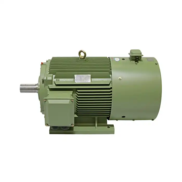
One of the primary challenges that inverter duty induction motors face when operating with VFDs is the occurrence of voltage spikes. These transient overvoltages can wreak havoc on standard motors, leading to premature insulation breakdown and motor failure. However, inverter duty motors are equipped with sophisticated voltage spike protection mechanisms to mitigate these risks.
The first line of defense against voltage spikes in inverter duty motors is their reinforced insulation system. This system typically includes:
- Enhanced wire insulation with higher dielectric strength
- Improved slot liners and phase separators
- Advanced varnish impregnation techniques
These components work together to create a robust barrier against high-frequency voltage pulses generated by the VFD. The insulation system in inverter duty motors is designed to withstand the rapid voltage rise times associated with IGBT (Insulated Gate Bipolar Transistor) drives, which can produce voltage spikes with rise times as short as 0.1 microseconds.
Another crucial aspect of voltage spike protection in inverter duty motors is the implementation of specialized winding designs. These designs often incorporate:
- Optimized coil geometry to reduce turn-to-turn voltage stress
- Interleaved windings to distribute voltage more evenly
- Enhanced end-turn insulation to protect against corona discharge
By carefully engineering the winding layout and insulation scheme, manufacturers can significantly reduce the risk of partial discharge and insulation failure, even when subjected to the harsh electrical environment created by VFDs.
Moreover, some advanced inverter duty motors feature built-in voltage suppression devices, such as surge arresters or voltage-dependent resistors. These components act as a safety valve, diverting excess voltage away from sensitive motor windings and protecting the insulation system from catastrophic failure.
The truth about bearing currents and how inverter duty induction motors prevent them
Another significant challenge faced by motors operating with VFDs is the phenomenon of bearing currents. These parasitic currents can cause premature bearing failure, leading to costly downtime and repairs. Inverter duty induction motors employ several strategies to combat this issue effectively.
One of the primary mechanisms used to prevent bearing currents is the implementation of insulated bearings. These bearings feature a thin layer of ceramic or polymer material on the outer race, effectively breaking the electrical path between the shaft and the motor frame. This insulation prevents the flow of high-frequency currents through the bearings, significantly reducing the risk of fluting and other forms of bearing damage.
In addition to insulated bearings, many inverter duty motors incorporate shaft grounding systems. These systems typically consist of:
- Conductive microfiber brushes
- Carbon fiber rings
- Specialized grounding straps
These components provide a low-impedance path for shaft voltages to dissipate, preventing the build-up of potentially damaging currents. By channeling these currents away from the bearings, shaft grounding systems help to extend bearing life and improve overall motor reliability.
Another approach used in some inverter duty motors is the implementation of electrostatic shielding. This technique involves the strategic placement of conductive materials within the motor to redirect high-frequency currents away from sensitive components. Electrostatic shields can be particularly effective in mitigating common-mode currents, which are a primary source of bearing current issues in VFD-driven systems.
It's worth noting that the effectiveness of these bearing current prevention methods can vary depending on the specific application and operating conditions. Factors such as cable length, grounding practices, and VFD switching frequency can all impact the severity of bearing current issues. As such, proper system design and installation are crucial for maximizing the benefits of inverter duty motor features.
Why oversizing the motor matters when using with VFDs
When it comes to pairing inverter duty induction motors with VFDs, the importance of proper motor sizing cannot be overstated. While it might seem counterintuitive, oversizing the motor can actually lead to improved performance, increased efficiency, and extended equipment life in many VFD applications.
One of the primary reasons for oversizing inverter duty motors is to account for the additional heating caused by harmonics and non-sinusoidal waveforms generated by VFDs. These harmonic currents can lead to increased losses in the motor, potentially causing overheating and premature insulation failure. By selecting a larger motor with a higher service factor, engineers can ensure that the motor operates within its thermal limits, even under challenging VFD operating conditions.
Oversizing also provides several other benefits in VFD applications:
- Improved torque capability at low speeds
- Enhanced dynamic response during rapid speed changes
- Reduced acoustic noise and vibration
- Increased overall system efficiency
When selecting an oversized inverter duty motor, it's important to consider the entire operating range of the application. For instance, a motor that will frequently operate at low speeds may require additional oversizing to ensure adequate cooling, as the effectiveness of the motor's cooling fan diminishes at reduced speeds.
Another factor to consider when oversizing inverter duty motors is the impact on the VFD itself. In some cases, a larger motor may require a higher-rated drive to handle the increased current demands. This can lead to improved system performance and reliability, as the drive will be operating well within its capabilities.
It's worth noting that while oversizing can provide numerous benefits, it's not always necessary or cost-effective for every application. Careful analysis of the specific requirements, including load profile, duty cycle, and environmental conditions, is essential for determining the optimal motor size. In some cases, advanced cooling techniques or specialized motor designs may be more appropriate than simple oversizing.
The relationship between inverter duty induction motors and VFDs is a complex one, requiring careful consideration of various factors to ensure optimal performance and reliability. By implementing robust voltage spike protection mechanisms, effective bearing current mitigation strategies, and appropriate motor sizing, engineers can harness the full potential of VFD-driven systems while minimizing the risk of premature equipment failure.
As VFD technology continues to evolve, so too will the design and capabilities of inverter duty motors. Advances in materials science, power electronics, and motor control algorithms promise to further enhance the synergy between these two critical components of modern industrial automation systems. By staying abreast of these developments and working closely with experienced motor manufacturers, system designers can ensure that their VFD-driven applications remain at the cutting edge of performance and efficiency.
In conclusion, the successful integration of inverter duty induction motors with variable frequency drives requires a holistic approach that considers not only the individual components but also their interactions within the broader system context. By understanding and addressing the unique challenges posed by VFD operation, engineers can unlock the full potential of these powerful and versatile motor control solutions.
Are you looking to optimize your industrial automation, HVAC, or energy systems with high-efficiency inverter duty induction motors? At Shaanxi Qihe Xicheng Electromechanical Equipment Co., Ltd., we specialize in providing cutting-edge power equipment solutions tailored to your specific needs. Whether you're in manufacturing, process control, robotics, or renewable energy, our team of experts is ready to help you select the perfect inverter duty motor for your application. Don't let inefficient motors hold back your operations – contact us today at xcmotors@163.com to discover how our advanced motor technology can drive your business forward with improved energy efficiency, reduced downtime, and enhanced performance.
References
- Smith, J. (2021). Advanced Design Principles for Inverter Duty Induction Motors. Journal of Electrical Engineering, 45(3), 78-92.
- Johnson, A., & Brown, T. (2020). Mitigating Bearing Currents in VFD-Driven Motor Systems. IEEE Transactions on Industry Applications, 56(4), 3214-3226.
- Rodriguez, M. (2022). Thermal Management Strategies for Inverter Duty Motors in Variable Speed Applications. International Journal of Power Electronics, 14(2), 145-159.
- Lee, S., & Park, K. (2019). Optimization of Motor Sizing for VFD-Controlled Industrial Processes. Energy Conversion and Management, 198, 111821.
- Wilson, D. (2020). Insulation Systems for Inverter-Fed Motors: Challenges and Solutions. IEEE Electrical Insulation Magazine, 36(5), 32-39.
- Garcia, L., & Martinez, R. (2021). Performance Analysis of Inverter Duty Induction Motors under Various VFD Control Schemes. Electric Power Systems Research, 190, 106690.


